We’ve been working on reverse-engineering a Smart ForTwo electric drivetrain with the goal of open sourcing the vehicle components for general electric vehicle conversions or other hobbyist uses. There are four main components in the Smart’s electric drive train: DC-to-DC converter, AC system, vehicle charger, and the drive motor with controller.
The DC-to-DC converter has the same function as an alternator for a standard gas powered vehicle: it supplies power for and maintains the charge of the 12 volt system. The air-conditioning (AC system) keeps the car cool on a warm day. The vehicle charger charges the high voltage battery pack from either a 110 or 220 volt standard household outlet, or from a standard J1772 vehicle charging station with the appropriate plug.
Note: All work completed so far has been to get the components functional while separate from the car, nothing has been done to decrypt CAN data packets. We are not addressing the battery pack for this vehicle. Any and all use of vehicle power sources and or components including the batteries, are up to the discretion of the user.
To accomplish our goals we needed a couple test drive trains, a working vehicle and some way to ‘sniff’ the CAN messages. The CAN capture and control device of our choice is an Arduino DUE combined with EVTV’s CANDUE. Along with this hardware we needed some software. There are huge cashes of Arduino sketches available. They’re are like apps for your smart phone and work much the same way. Each one is designed to do one or more specific tasks like turn on a switch or make your Lego Techniques do the Hokey Pokey. Sketches are written, edited and uploaded through Arduino’s IDE (integrated development environment). We used GVRET software version 334 developed by Collin Kidder. This library can be download at https://github.com/collin80
These are some of the basic tools you’ll need to either ‘sniff’ or run many of your open-sourced components:
THE COMPONENTS
The DC-to-DC converter takes the high voltage DC from the vehicle’s battery pack (for the Smart, this voltage ranges from about 280 to 380 volts) and converts it to 12 volts (actually about 13.6 volts) to power all of the 12 volt systems like head lights, radio, power windows, etc.
That the DC-DC is a fairly straight forward unit to get running, although a bit hard to get at since it is a board mounted inside the controller casing which is a part of the motor/controller system. To use this unit independently of the inverter/motor you’ll have to install it into it’s own weather-proof housing and supply-appropriate cooling and electrical connectors and ports. You can see the high voltage plug wires which are labeled + and – (photo below). These labels can only be seen from the inside of the inverter case. Power must be supplied in the proper polarity and range between 280-380 volts DC (the full range of these numbers has not been verified). There are also two CAN wires, CAN high and low, pins 16 & 17 respectively on the main 23 pin inverter wiring connector. The DC/DC requires you to send the CAN message 112, included in the CAN file. This message will turn the unit on and off. Onboard software does all the necessary load sensing and automatically adjusts to the load being demanded.
Once you supply high voltage power and the CAN 112 message, that its, the DC/DC should turn on and supply 12 volt output for your system (note: the 12 volt output lines are located next to the high voltage input lines, they are the smaller plastic twist lock connector coming off of the motor/inverter casing.
When supplying high voltage power to the DC/DC converter, like most high voltage components that contain capacitors, a pre-charge resistor should be used.


The AC system follows the same basic strategy as the DC/DC converter to get it running. High voltage input (+,-), needs to be supplied to the orange high voltage plug (pictured below), CAN high and low inputs/outputs need to be sent to pins 2 and 3 and you need to supply 12 volts and ground to pins 1 & 4 (see pin out below). Again since this system runs off high voltage the same precautions, personal and electrical, apply; namely a pre-charge resistor and isolation between the high voltage and you are both a good thing to have.
The high voltage (see pic) must be within the range marked on your AC unit (since the Smart operates between 280 and 380 volts, I’d start with that range). The interlock wire loop to override the interlock should be left open (don’t do anything with them) sending the appropriate CAN inputs. In this case there are 3 messages being used: 0x244 is the start command for the compressor, 0x392 acts as the run command and message 0x452 is the response to the car from the compressor.
By hooking up the AC compressor in this manner and sending the commands listed, you will turn on and run your AC compressor. However, this has noting to do with the environmental controls, fan speed, compressor variable load control; that will all depend on the ‘car’ side of your AC system (e.g. thermostats, defrost settings, etc.) that you set up in your vehicle and will be specific to your system. I recommend using low tech to solve this problem, at least initially, to get it working and tweak it as time allows. To do this, combine the Smart’s AC with something like the Vintage Air evaporator and dash control system. They’re designed to be installed in vehicles that never had AC so they will not be tied into other systems, thus reducing the number of problems with getting the system up and running by some logarithmic amount (or a lot-ish if you’re interested in the technical term).
(See pin out pics) No, I have not put the Smart’s AC into another vehicle yet. We have only got it running. Let me know once you’ve fully integrated a system along with the info on how you did it and we’ll add it to our post as an option for others. (Keep it open source/keep it going!)


The 3.3 kW charger is slightly more complicated than the AC system…but not much.
The charger input has a 5 pin connector, the J1772 plug, that accepts power from an AC power source that can range in voltage from 100 to 250 volts, which includes the common 110 and 220 household voltages. The three larger pins are for power and ground. Line 1 and line 2, labeled as pins B and C, are the 110 power input lines (one from each leg of 110 power coming into your household breaker box. Pin A is the ground, see picture for pin out (this diagram is looking at the input of the charger with the cord removed). Of the two smaller pins, only one is used. It’s a communication wire used for the J1772 protocol handshake and interlock. This requires a known resistance, as per J1772 protocol, be put on the AC input hooked between the pilot and ground pins (I think it’s about 881.6 ohms, but don’t quote me on that, and don’t forget your diode). The high voltage power output ranges from 278-380 volt DC and goes directly to the battery pack. Some choose to put a charge fuse or Kilovac on the output side of the charger between the charger and battery pack. It’s up to you if you want to do this or not –safety is in the hands of the builder. ! Always check output polarity before hooking up to your system !
Next: the CAN communication wires and interlock. This system communicates using standard J1772 protocol. The CAN message you need to send to enable the charger is 122 (see pin out pic below). We currently have no idea what CAN message reports back to the vehicle for the charger. So far none have been required during our testing. The charger automatically adjust to load requirements. The only other thing you need to make the charger work is to supply power to the high voltage interlock. A 1.15 volt power supply is needed with the +1.15 hooked to pin 6 and the ground (-1.15) hooked to pin 1.


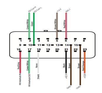
The drivetrain is a compact unit consisting of the motor/inverter/and DC/DC converter all in one. It has a 2 wire high voltage input with interlock (interlock on high voltage plug is not necessary to run system) from the battery pack, a 2 wire twist lock 12 volt output from the DC/DC converter and a 23 pin communication terminal that handles all CAN communication, 12 volt Power and Grounds, and high voltage interlock loop. Of these 23 pins only 11 need to be used, 2 of them are grounds (pins 14 & 15) and must be bonded to the DC/DC converter negative output (you may also want to bond the CAN shield, pin 18 to ground; we think it’s a good idea). 4 of the pins are 12 volts +Positive+ (pins 5, 6 ,21 & 23). Pins 2 & 10 are the CAN high and low. And finally the high voltage interlock, pins 16 & 17, which need to have 1.15 volt power supplied, +1.15 volts on pin 16 and 1.15 volt ground on 17.
To enable the drivetrain, a timed ignition signal must be given at the appropriate time with the CAN signals or nothing will happen. We used GVRET software version 334, which now has digital toggle functionality. This was been set up to inject a CAN signal when the ignition line is commanded to turn on from the CAN data we captured turning on an ignition relay supplying PIN 21 with the required 12 volt signal. (We created a CAN message, giving it identifier 101, that tells the ignition relay to come on, we did this by adding a line to the CAN data and building a breadboard with a relay on it which puts 12 volts on the ignition when commanded on).
So far we’ve got the drivetrain spinning on its own using the procedure above, and the CAN captures (link to files at bottom of post). There are many more steps before this will be ready to integrate seamlessly into a build, such as incorporating the acceleration/deceleration signal to acquire speed control. But with the information we’ve supplied here you should be able to run all of the components listed independent of the Smart ForTwo, including the DC/DC converter, AC, charger, and drivetrain.
As I said earlier, all work completed so far has been to get the components functional while separate from the car, nothings been done yet to decrypt CAN data packets. We are not addressing the battery pack for this vehicle, any and all use of vehicle components, including batteries, are up to the discretion of the user.
As always, have fun and best of luck to you. I hope to hear about many successful builds stemming from this work. If you stumble across anything interesting along the way, please share and we’ll add those morsels to our blog so that others can continue to take advantage and learn from the work that’s been done so far.
What’s Next???
We want to make a board that ‘seamlessly’ integrates this info into an easy to use vehicle control module and see about making a portable supercharger– think trailer with a big plug, utilizing a stack of the smart chargers that will supply 90-120 kWs of fast-charging potential. Instructions on how to do-this-yourself are coming in a later blog post. Now where did I put my KCMIL2000 wire Krimper?
NOTES:
The CAN message baud rate was 500 kbps.
The high voltage you supply to the motor has to be within 1 volt (ish) of what the voltage was at during the CAN capture or your motor will not turn! What’s the voltage at which we ran our CAN data captures? That’s an Easter egg for you to find, shouldn’t be that difficult. 😉
Download files (800 kb zip file).